Autonomous vehicles and mobile robots (an autonomous vehicle is a car-shaped robot) have different ways of calculating their own location and different localization systems.
The common navigation systems in robots use a combination of the following sensors to determine self-localization, to know their destination, and to create a path to reach the destination:
- GPS
- Cameras
- Lidars
- Radars
- IMU
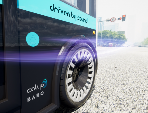
In this post, we explain the self-localization techniques we use in our autonomous platform, the BARO CAV, improving navigation and localization with LITA.
One form of location is through implementing sensors such as lidars and radars. But in wide-open environments, these sensors are useless because they work by bouncing light waves and radio waves off objects.
Another form of detection is through a global positioning system (GPS) device. However, GPS signals malfunction indoors, such as in factories, tunnels, or underground parking lots, and they malfunction when it is cloudy, so the cloudier the day, the stronger the GPS anomaly. GPS does not work well when there is a lot of interference from buildings – just walk a few minutes in the middle of London and you’ll find that the GPS of your cell phone gets disoriented and experiences long delays in determining the correct location.

01. GPS
When the robot does not know where it is and cannot calculate its position, it gets lost and stops because it does not identify its location.

02. GPS SIGNAL GETS BLOCKED
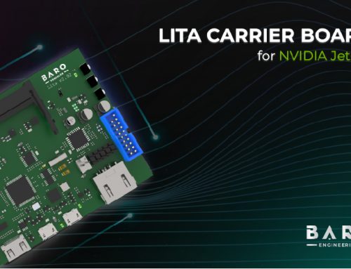
To solve these problems, our LITA Carrier Board combines GPS with an inertial measurement unit(IMU), and improving navigation and localization, so the vehicle learns its location using acceleration and turn data, starting from the last point where it had a GPS signal.

03. IMU
But the question is: “If I put the LITA Carrier Board in my mobile robot, how do I calculate how far it has advanced?”
This IMU connects to the tachometer and thus to the wheel and allows you to know how far the vehicle has travelled and how many degrees it has turned to determine the direction. This process of calculating the current position of a moving robot by using a previously determined position and then calculating position using the speed, direction, and elapsed time data is called dead reckoning. Dead reckoning technology allows us to determine the location indoors, in parking lots, warehouses, and roofed facilities; however, the GPS with IMU must at some point have a connection to know its initial position.

04. IMU measures speed, direction and other data.
Another technology is the Indoor Positioning System, based on RTK devices. With this technology, the robot’s GPS does not require a satellite signal but instead requires signal-generating devices installed in the place and connected with the GPS signal to give the location to the vehicle. This technology can be precise, with up to 2 cm of accuracy, but it is also more expensive. It requires not only the installation of the devices but also the analysis of their location and their corresponding maintenance, and in the case of a vehicle, it serves only for that place.
In our autonomous platform, the BARO CAV, we use the two IMUs of the LITA Carrier Board: the IMU provided by the onboard GPS and an additional IMU from TDK InvenSense. In this way, we can avoid installing RTK devices for indoor positioning and, by comparison, obtain better location accuracy. By having different technologies, the combination of both IMUs processed through a Kalman filter will give us greater certainty of the real position of the robot improving navigation and localization. Because these devices within the LITA Carrier Board (GPS and IMU) are automotive grade, they reduce the chance of interference.
How exactly does GPS work with dead reckoning?
The internal IMU of the GPS plus the tachometer estimate the position using a Kalman filter. Thanks to the algorithms of this GPS, the device gives the software a position expressed in longitude and latitude, like the position provided by the satellite, but the device explains in the data that it is an estimated position, not the real one based on the satellite.
We know the GPS position may have anomalies, but we can improve the position calculation capacity by combining it with the IMU’s acceleration and turn calculation. We can also improve the accuracy of the positioning data by reducing the number of cables inside the robot; LITA is an integrated device, so we can obtain data in real-time by reducing the installation and integration of several boards.
We know that when entering the sensor fusion stage within the positioning and location algorithms, all devices need to deliver the date and time the data was taken; if a sensor delivers data at a different time, the position will be wrong, and the value for each sensor at the same moment will be imprecise.
Improving navigation and localization systems
Our BARO CAV platform uses the Ethernet and GPS of the LITA Carrier Board connected to the lidar to achieve proper time synchronization. If the device is a radar, for example, the LITA Carrier Board also has a high-speed CAN-FD interface working at 5 Mbps that allows us to collect the information from the mmWave radar at a reasonable speed to be useful when the robot or vehicle is moving at a high speed.
I hope you find the explanation of GPS with dead reckoning useful and now understand how we use it in the LITA Carrier Board and our autonomous platform for self-driving cars, the BARO CAV, and how a second IMU is highly recommended to properly estimate the position of the robot and reduce sensor error. If you have any questions, leave a comment and I will try to clear up any doubts.